• Sign Up! To view all forums and unlock additional cool features

    Welcome to the #1 Ford Fiesta Forum and Ford Fiesta community dedicated to Ford Fiesta owners and enthusiasts. Register for an account, it's free and it's easy, so don't hesitate to join the Ford Fiesta Forum today!


Spark plug wire resistance

OP
Daveb40258
Messages
46
Likes
8
City
LOUISVILLE
State
KY
Country
United States
What I Drive
2016 Fiesta Titanium Hatchback
Thread Starter #21
The damage I see of your incident tells me the A/C - ABS braking system or the passenger side (internal fuse and relay box and even the BCM) can be affected by this.

You may not have issues with the PCM, but with the flex/bending of the passenger side and how it can affect the Body control Module - the inside fuse box (behind the Glove box) may hold clues on this.

Andy,
Thanks for the reply. I'm not sure but perhaps you missed it or I may not have told you, the accident that the happened was over a year ago. 3/29/23. Keep in mind when I received the payout on that it allowed me to do a complete tune up.
Starting with wiring that led light to the same fuse that supplies the components that are throwing all the codes, and this particular problem started in April 2024.
Now in April a month after the led wiring my daughter tore off the passenger side mirror. Totally unrelated to the 2023 accident.
It was the 2024 incident, the mirror, where the very next day I had to jump start the car. After that all this cascading of codes started. I already checked every fuse in every box on the car. Surprisingly that box behind the glove box was the hardest to test. The way it sits was nearly impossible to get comfortable testing each fuse. Maybe I should check again but for the record it was tested once.
I hope it's just me but I'm feeling like your just as frustrated trying to help as I am trying to diagnose.
Please don't give up yet.
I haven't.
Alldata has given me a bunch of information and step by step troubleshooting guides. (If yes go to xx if no go to xx type of troubleshooting)
It's going to take some time to do all this as a lot of it is pin-out troubleshooting. Remember I said electrical is not my strong suit.
With that said can you give me any advice on how to do all this testing without accidentally blowing the PCM?
Do I disconnect the PCM to check the pins forward and back checking for shorts or broken wires?
I also do not know why the PCM and other control modules will not reset after a week long disconnect of the battery? I feel like if I could start with a clean slate these issues may solve themselves.
I learned that even in a crank no start the PCM will still throw codes. Like the new P06B8 and P0882 codes.
I have accepted the fact that due to my lack of experience with new vehicles this is going to be a very long process.
Please, I do not care how long of an answer you give I will read the entire post.
Can you give me your best advice for carrying out this kind of diagnostic troubleshooting?
Thanks.
 

Handy Andy

Well-Liked Member
Premium Account
Messages
1,723
Likes
1,287
City
Grand Rapids
State
MI
Country
United States
What I Drive
2018 Ford Fiesta SE HB
#22
These thoughts are just my own and are only related knowing some of them have been tried with good success while others have only achieved one-time correction and I was left to live with the simpler facts that this is the way it was made, so live with it.

There are Youtube "hacks" about throttle relearns using the Key-to-on then quick-tromp of the throttle 3-times then START to help the system with throttle response.

In light of those types of hacks...

I also have a few thoughts on a thread about how to reset the memory of a system by forcing the drain using a simple circuit tester that uses a Filament (light bulb) that when it's cold or little power is applied (low-voltage and or current) across itself from a terminal to ground the bulb won't light ,but acts like a short circuit to help force a reset.

So in the research of that P06B8 code - tells me the Nonvolatile NVRAM is corrupted or is having problems.

So I have used the device in a thread...
https://www.fordfiesta.org/threads/body-control-modual.8227/post-20339

The above thread is long and although talks about system grounds, you have seems to have fixed some, but there are many more in the vehicle for the various systems - up to and including the Fuel Pump and even the under-dash Brake and Throttle ground bonding points.

Why this comes up is to help you find a method of using that circuit tester to provide a short across the terminals but back at the Starter and Alternator post section - not just the battery positive to ground. ()you seem to have done that to a point) - why? A resistive junction can occur which can lead someone to think they can't drain the memory to force a reset relearn - all because of there is enough resistance across a junction at one of the battery terminals to let the keep alive battery keep the corrupt memory alive as a process of trying to move data to a more secure permanent location - this is why the code pops up. It knows something is bad, and it is not set up to just clear it - it tries to log it as an error but it cannot finish the job.

I'll let you digest the info and see if we can somehow develop a plan to attack this.
 
OP
Daveb40258
Messages
46
Likes
8
City
LOUISVILLE
State
KY
Country
United States
What I Drive
2016 Fiesta Titanium Hatchback
Thread Starter #23
@scotman And Andy,
Yes it is 249am 5/24/24.
First let me apologize. I came here for help and yes I have done a lot trying to fix this but I may have sounded like a "know it all" just because a YT video told me otherwise I apologize. On that note thank you for linking me to that post. And especially for taking the time to overlook my ignorance and try to help. Now back to that thread.
I can't tell you the countless times a soda has been spilled in the center console. The many times I've sprayed water directly under the door to make sure I get all the salt from winter weather.
I never knew that a circuit tester can be used in such a fashion. Thank you for that as well.
I also did not know that both sides of the fuse should be tested and that's just plain common sense. When I was much younger and cars were easier to work on remember this girl I was dating asking how I could possibly know so much about certain repairs like brakes and anything with a bunch of parts. I always replied just use common sense . If you have a bad memory lay the parts out as you take them off that way you have a diagram of the area your replacing. I have apparently lost some of my common sense.
Ok so I will hunt and search and use the Alldata wiring diagrams to track down every ground I can find. As I read on a couple things came to mind.
1) mine is a push button start. You know when u leave the car running and shut the door it gives 2 horn blows?
Ok I didn't think about this but the car isn't even running but after every time I try to start it I shut the door and 2 horn beeps. (Does this tell us something)
2) if the battery is connected and I'm checking for power all of a sudden the chimes will go off in the cab. Usually the door has to be open and the chimes warn you of: hey when u shut me off last time you left windows down. Or what ever. I don't think random chimes should be happening. Right?
3) replacing that side mirror was a absolute nightmare. She hit it enough that the bolt that held the old mirror in was bent and it was not fun trying to get it out. I tried impact guns all kinds of tools and finally got it out with some cone shaped tool for removing stripped bolts. Every connection on the door uses connectors no bare wires EXCEPT the bare wires from when the mirror was just barely hanging on the door. I thought the dead battery the day after was caused by the bare wires touching the body. It just didn't sound right how a mirror could cause all this . But maybe it could have especially if those wires are always charged.
Then I read about intermittent alternator charging. Hmmm where have I heard that word before lately.? Oh I remember P0369 circuit B bank 1 CMP INTERMITTENT.
I hope I'm on the right path. Let's tackle this thing .
1 I will find all the grounds and clean them and possibly re solder.
2 pull all the relays and fuses check for corrosion.
3 test all the fuses correctly
4 use the circuit tester as a way to :
A check for any open circuits
B use the tester as a drain to execute a reset
5 report any findings so we can move on
Does this sound good? Am I missing anything?
Thanks Andy for the reply.
 
Last edited:

Handy Andy

Well-Liked Member
Premium Account
Messages
1,723
Likes
1,287
City
Grand Rapids
State
MI
Country
United States
What I Drive
2018 Ford Fiesta SE HB
#24
Hold...

if the battery is connected and I'm checking for power all of a sudden the chimes will go off in the cab.
There may be more to this than what you have already discovered.
1716545972920.png

We don't have your car in front of us, but it may be that your conditions are due to crushed wiring or cut wires from the accident that may seem ok, they look intact. But they may have be compromised.

If you stripped off the sleeve of the wire - you'll find green or black corroded copper wiring causing intermittent problems and worse, the harness itself might be compromised and it's falling apart within the loom and cover sleeves.

IF the insulating protective cover of the wire was punctured, salt, water or moist air can enter and stay in the inner sleeve to contaminate/acerbate the copper wiring and corrode it from within.

NOW YOU KNOW, YOU MAY NEED TO LOOK FOR LOOSE WIRING CAUSED BY THE ACCIDENT THAT HAS NOT YET BEEN DISCOVERED.

I'm adding more...

Your other clues are - the horn toots when you think the engine is off.

The NVRAM is not resetting can be caused by:

Wiring or relays - keeping power applied - when the system tells it to shut off it can't because the system never can communicate with it due to the bad wiring caused by corrosion and accident - accrued together - to make this appear.

You may need to pull relays and check to see if the horn toots still even after you've shut off the engine - you'll have to re-create the scenario to get this to repeat but it can offer more clues as to which systems are "still alive" when they shouldn't be.
 
Last edited:
OP
Daveb40258
Messages
46
Likes
8
City
LOUISVILLE
State
KY
Country
United States
What I Drive
2016 Fiesta Titanium Hatchback
Thread Starter #25
Hold...


There may be more to this than what you have already discovered.

We don't have your car in front of us, but it may be that your conditions are due to crushed wiring or cut wires from the accident that may seem ok, they look intact. But they may have be compromised.

If you stripped off the sleeve of the wire - you'll find green or black corroded copper wiring causing intermittent problems and worse, the harness itself might be compromised and it's falling apart within the loom and cover sleeves.

IF the insulating protective cover of the wire was punctured, salt, water or moist air can enter and stay in the inner sleeve to contaminate/acerbate the copper wiring and corrode it from within.

NOW YOU KNOW, YOU MAY NEED TO LOOK FOR LOOSE WIRING CAUSED BY THE ACCIDENT THAT HAS NOT YET BEEN DISCOVERED.
Andy,
I'm just trying to determine which "accident" you're referring.
The semi backing into me at about 3 mph in 2023 and was only body parts no exposed wires
Here's what was replaced in 2023: at 93k miles
(Bumper cover, hood, headlights, fog lights one needed a new connector, upper and lower grille, radiator mount, front struts, alignment ( both done at the best front end shop in Louisville), lower control arm, front sway bar stabilizers, new wheel, and various clips.
There were no punctured fluid containers, no engine damage, no windshield damage. It took about 30 days to get the right parts and install. I used the extra repair money for plugs, wires, a vapor canister by the fuel tank that I broke backing into a ditch delivering pizzas during a rain storm. Brakes all around, air filter, cabin filter, HVAC Door actuators (blend and main),and an oil change.)
Or
. The mirror incident at 113k miles. With every wire exposed that is inside the assembly. Replaced mirror assembly.
Edit: btw the chime thing I mentioned a few posts sgo. I was working near the battery from the Bank1 CMP to the evap purge valve. I did a wiggle test to try and recreate those chimes to no avail. But that area will be the first place I look after all the grounds.

Thanks for your super quick reply .
David
 
Last edited:

Handy Andy

Well-Liked Member
Premium Account
Messages
1,723
Likes
1,287
City
Grand Rapids
State
MI
Country
United States
What I Drive
2018 Ford Fiesta SE HB
#26
Well, I'm referring to accumulated damages - the front nose section also has the SRS airbag sensors and several routes for the harness (Knock Sensor, Horn, Head Lamps to name a few) and towards and behind the Right Strut tower towards the mid-level height - in the entry point to the BCM module behind that firewall bulkhead and ABS assembly to just in front of it.- so this may be accumulated damages due to the accident.

How is the radiator and AC doing? The hit may not have "penetrated", but if you have taken the nose pieces off, you'll see the AC unit it's metal, but the "basket" it rests in, is plastic, so there's a lot of wiggle room due to the softer holsters that both the Condensor and Radiator rest on.
 

scotman

Well-Liked Member
Messages
1,880
Likes
1,594
City
Grass Lake
State
MI
Country
United States
What I Drive
2011 Fiesta SE hbk Blue
#27
The electrical connectors in our Fiesta's are very weathertight. Way better than anything back in the 1980's. Pinched, broken or wire rubbed raw of insulation are very problematic. But, those issues seem to be an exception rather than a common occurrence. If those things happen it's usually because someone didn't put the harness retainer clip back in its proper place or broke the retainer clip and left the harness loose to be pinched, melted or snagged etc.
The 600 pound gorilla from the Fiesta's electrical systems perspective is the ground connections. They are naked compared to even the flimsiest looking single wire tiny connectors in the audio head unit.
As the ground connections are exposed to the elements the corrosion begins to effect the resistance in the system. You could compare it to a drain pipe that slowly becomes plugged up.
The problems become amplified in circuits that have very low voltage requirements, such as Canbus communication signal wires.
While their voltage requirements are small, those required voltages are very precise and must be reliable and stable.
The entire system is reliant upon a storage battery that is in good condition and capable of delivering a steady supply of electricity. The battery also acts as a buffer for voltage drops or spikes when the alternator is commanded on. Voltage drops/ spikes are the mortal enemies of Canbus networked cars. Most electrical component failures occur because of unstable voltage.
In Canbus communication, signal power voltage is very comparable to voice volume. The control modules and relays, capacitors etc are created to understand their control signals only at specific value or volume. If the signal voltage is too low, the message is either lost or garbled. If the signal voltage is suddenly spiked, it is like the control modules are being screamed at. Also not good. Those are the conditions that generate communication errors at best and fried or stuck capacitors and other things at worst.
I hope this helps people to understand why the battery condition and ground connection cleanliness is so very important to maintain on their Fiesta. The Fiesta is almost completely dependant on that for reliable functionality of 95 percent of its systems and features.
 
OP
Daveb40258
Messages
46
Likes
8
City
LOUISVILLE
State
KY
Country
United States
What I Drive
2016 Fiesta Titanium Hatchback
Thread Starter #28
Well, I'm referring to accumulated damages - the front nose section also has the SRS airbag sensors and several routes for the harness (Knock Sensor, Horn, Head Lamps to name a few) and towards and behind the Right Strut tower towards the mid-level height - in the entry point to the BCM module behind that firewall bulkhead and ABS assembly to just in front of it.- so this may be accumulated damages due to the accident.

How is the radiator and AC doing? The hit may not have "penetrated", but if you have taken the nose pieces off, you'll see the AC unit it's metal, but the "basket" it rests in, is plastic, so there's a lot of wiggle room due to the softer holsters that both the Condensor and Radiator rest on.
@scotman ok guys thank you and Andy what your saying now makes a lot of sense.
So I took a break for a while. I have had 3 neck and 3 low back fusions. Continuous leaning and other positions have kinda knotted me up. During that time I tried reading as much as I could trying to understand the wiring and testing and troubleshooting components.
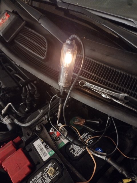
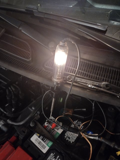
The first thing I did was the test light between the negative battery terminal and the disconnected negative wire. And got a bright light . I started pulling fuses and the light got very dim when I pulled fuse #3 under the hood:

60 amp passenger compartment fuse box.

Ok before I go any further. Do I put that fuse back in and pull the fuses under the glove box. I Included pics of the test light before and after but since my phone sucks it doesn't quite show the considerable difference in before and after fuse removal.
Just so I understand. Could this drain be reeking havoc on why it won't start? This is the first time finding something bad where I actually cheered. I hope this is good we are narrowing it down...... Right?
Oh the radiator and ac are perfect.
IMG_20240527_214610325_HDR.jpg IMG_20240527_214538563_HDR.jpg
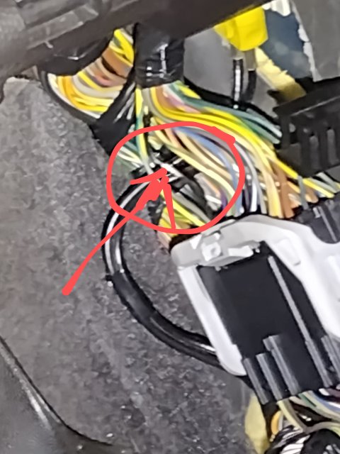
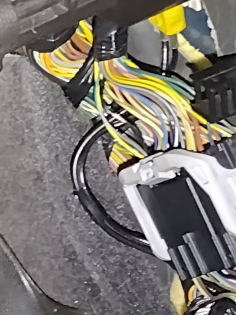
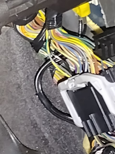
Edit: (new pics) ok so I pulled out each fuse and relay under the glove box and nothing made the light go out . However I found this very suspicious wire. Almost looks like a bare wire wrapped with black electrical tape.
Sigh I thought we were getting close.
Well I can't reset shit with a parasitic drain or short .
Oh isn't there supposed to be a fuel pump reset button around that harness somewhere?
Btw that happens to be the side where the side mirror was torn off.
I'm wondering if I should take that door panel off and see if I may have crimped or broke a wire putting it back together . Dumb question I'll do that as I wait for a reply.
Any thoughts?
IMG_20240527_232119244~2.jpg IMG_20240527_232119244.jpg
 
Last edited:
OP
Daveb40258
Messages
46
Likes
8
City
LOUISVILLE
State
KY
Country
United States
What I Drive
2016 Fiesta Titanium Hatchback
Thread Starter #29
W
The damage I see of your incident tells me the A/C - ABS braking system or the passenger side (internal fuse and relay box and even the BCM) can be affected by this.

You may not have issues with the PCM, but with the flex/bending of the passenger side and how it can affect the Body control Module - the inside fuse box (behind the Glove box) may hold clues on this.
Wow Andy you kinda nailed it way back here. But there was no change trying to get the light to go off at the inside fuse box . I don't get it
And why a year passed before any problems?
Maybe the extreme force trying to get that mirror out ?
 

Handy Andy

Well-Liked Member
Premium Account
Messages
1,723
Likes
1,287
City
Grand Rapids
State
MI
Country
United States
What I Drive
2018 Ford Fiesta SE HB
#30
Being a Fiesta owner, I too learned a LOT about how this newer wire technology and the wire/jacket - sleeve stuff works.

This is way different from the older wire/copper strands we used to work with in electronics (I come from a background in communications) where wire "strands" themselves were quite long and on a uniform thickness when it comes to bundled strands of wire tightly wound in a plastic sleeve jacket.

Now, these newer wires in the looms are made more "organically" than many like myself are comfortable with. They have a "soy-based" material that although is durable and is watertight, is not impervious to UV and other types of chemicals - like simple salt and water - which affect the older sleeved wires much less, until it's compromised - then both types of sleeves are off to the races when it comes to deterioration of the copper conductors.

So when it comes of the "made in USA" versus that of the foreign arrivals, the foreign materials win, due to less-cost and better for the environment. Which sucks - little effort is placed on the QUALITY the copper and the strands are in the bundle.

It seems that the copper strands are more like shards and spider web-strand thin lengths are flexible, but offer less "body" (Read:Malleability and ductility - bend and retain shape unless molded using heat molten-reformed) and much lower ability to withstand the environment (only saving grace is the lighter materials) - then older wire which used the strands own ductility, tensile strengths and uniformity in quality control held its shape - that when sleeved, fared better but required less of the sleeves ability to provide the strength/support and protection - for the copper on the older wires was of a heavier (thicker) AWG wire and was able to retain it's shape on it's own versus using the sleeve to keep it together.

So when you ask the question about why a year later, I'm doing my best just trying to keep the system I still have intact for many of the systems I've had issues with from the start had to be taken care of by my own efforts - no one else at Ford even batted an eye about this.

So this, like my own share of issues, have been cumulative - added-together - to give us this net sum of poor quality workmanship that really is not of the workmanship, but of the limitations of this design applied, to try to be environmentally friendly.

You're not alone in this.
 
Last edited:
OP
Daveb40258
Messages
46
Likes
8
City
LOUISVILLE
State
KY
Country
United States
What I Drive
2016 Fiesta Titanium Hatchback
Thread Starter #31
Imagine my excitement seeing you posted a reply. Sorry if I have nothing to add to your post except agreement.
I was looking more for comments on the test light parasitic drain test I performed.
So I am being told that I have to wait some 40 minutes for the BCM to discharge before doing that test.
Alldata suggests a MM with a 10 Amp capacity and anything over 50mA should be fixed.
If that's true then why is there still a drain after 6 days of the battery being disconnected?
Now regarding the Multi meter instead of a test light... Well I can't explain it but I got like maybe 50mA of draw. Normal range.
So why a bright light and when the fuse is removed a very dim light?
This is why electrical stuff really drives me crazy.
I still haven't removed the pass. Front door panel to re check that mirror and other wiring. The BCM is on the same side. And like I said I tried a air impact gun and even a hammer trying to get that old mirror off.
Can you tell me if these cars actually have a fuel pump reset at the pass. Side kick panel ?
Did you see that bare wire on the loom in that kick panel?

I usually don't proceed to the next area without getting your wisdom on a post.
Regardless of the time, I truly value your replies and anyone else that can help shed light on this mess.
Thanks again Andy
 

Handy Andy

Well-Liked Member
Premium Account
Messages
1,723
Likes
1,287
City
Grand Rapids
State
MI
Country
United States
What I Drive
2018 Ford Fiesta SE HB
#32
Fuel pump reset? Er, no, but some (Read titanium's and ST-lines) may have an electronic version of a fuel pump regulator that is linear as in variable pressures present due to the monitoring.

Otherwise the Fuel pump relay is embedded in the BCM itself - so there is a click-click that when you press your hand on the BCM you can feel as a tap when it clicks.

Later modules have a SSR (Solid State Relay) so this annoying noise gets done away with.

Not to be confused with an Air door and air-temperature vane in the same area that cycles - you can hear it quite pronounced when you're parked with the engine on.

The issue of the battery drain, I have yet to find the trick that the dealerships use, which lends me to think they use the Diagnostic connector and their tools to do this more than a simple drain down.

But I'm glad you found the circuit tester tool, for the light itself although is a tell-tale - it also provides the means to short out the leads of a terminal until it goes dead - with the light indicating the progress of the condition.

It can also help you find the other wires that are affected by the accident that are now showing their fail - so you're not done...

Neither am I.
(I have several events happening here one is the job I do so when summer hits things get real busy)

I will be adding more in another post in this thread - but one thing I do want to pass along is how the NVRAM - like on my Fiesta - I have to wait a h*ll of a long time for the drain to happen, and even then, the drain is kind of moot, for the issue of losing profile memory, it doesn't happen - because the system transfers the data in live data areas to NVRAM while it sleeps, much like an overlay - where the profiles are never reset, just given a chance to be modified - but never erased unless it's forced.

Forced? Yes, a dealership or a shop with more advanced tools - can use the Data-Link-Connector (DLC) the same one that your scan tool can read and reset DTC's and turn off the Check Engine light-only it can do this by telling the system to reset to an original profile and by doing so - then relearns the drivers way to drive and operate - until that is executed - the NVRAM will always make a copy of the live data as a safety feature to protect itself from lost data or tampering.

So what I'm trying see in your Test light photos - and yes, I do see the lamps differences in brilliance between the two - the only thing I'm trying to figure out is what or where you are testing FROM but I see the same, knowing the-TO as the battery post.

So to me, I think you're trying to show me the "Draw" as you describe in the post, so I will try to do the same tomorrow as time permits to show you the light level I have using a similar tester and bulb setup - but I do this as a remove the cable from the post - touch the tip to the battery post, and the clip to the ring of the terminal (cable) to show draw thru illumination.

The differences here is how (per what I described earlier) long you need to let the system sleep before the draw test can be done - so the setup and "Stage" have to be made, but then too, the engine run for a given length of time, then turned off, wait 5 minutes then remove the battery cable, but it's how it is removed is where some get thrown for a loop.

You have to do this with the hood open, but the doors closed, key in the ignition for the Start-run-stop - with the drivers window down - to reach thru to turn off the key - to start this process - your open the door - start the car as your normally would in the driveway - let it run for 5 minutes with you out of the car with the hood open and the doors closed - you can loosen the negative cable - but still leave it on the post - after that 5 minutes - reaching in thru the window - you shut it off and leave the cable on the battery but get ready to pull it - after 5 more minutes then you pull the cable - set up the tester - check the battery for light then again after the vehicle was sitting for another 5-minutes - with the tester left attached. At least this is how I do this for my own references.

The tester has to be left attached for the system to still retrieve power from the battery - there may be moments when the light will brighten then dim, sometimes will flash - this is part of the systems integrity check and diagnostics you don't always notice.
 
Last edited:
OP
Daveb40258

Daveb40258

New Member
Messages
46
Likes
8
City
LOUISVILLE
State
KY
Country
United States
What I Drive
2016 Fiesta Titanium Hatchback
Thread Starter #33
Wow.
Ok I attached the it opposite. The alligator clip is on the terminal and then I touch the other end of the light to the battery cable end. I thought it would be easier to wedge it in there so when I pulled the fuses on the inside I could watch the light.
Which didn't matter I didn't find the draw. I pull the fuse supplying the inside fuse box and the light dimms considerably. But leave that fuse in and pull fuses inside nothing happens to the light. I'm going to have to disconnect every connector on every circuit I guess.
If you look at the picture. That exposed wire was intentionally peeled back. I'm starting to wonder if this (some of this) was a pre-existing condition repaired at an earlier date.
I went on my Ford and there were no dealer invoices at all. I expected to see recall invoices at least.
Oh:
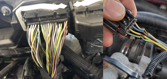
How do you unplug those damn connectors with the plastic retaining arm thingy. See picture. IMG_20240527_232119244.jpg
 
Last edited:

Handy Andy

Well-Liked Member
Premium Account
Messages
1,723
Likes
1,287
City
Grand Rapids
State
MI
Country
United States
What I Drive
2018 Ford Fiesta SE HB
#34
The connector is used for many of the "determined to be tight" connections. You can find it on the ABS unit, the Instrument Cluster and SYNC and even the BCM.

The Arm is a pivot, you lift it, rotates over the connector - which by it's design, that arm fulcrums against the case, pulling the connector off the pins inside it, then lifts up the connector straight up to reduce bending the tightly close spaced pins.Which you will see when you pry that arm up and as you lift, the arm rotates or pivots towards where the gray arms rest in the case.

  • To help, the "Arm" lifts the connector, but the wire bundle might be off 90 degrees to the direction the lift the arm makes - so you will see the connector lift out of the case, but the wire bundle - being stiff with wires, goes off in another direction.
  • When that arm is lifted you'll see the arm makes the connector follow a curved groove to reposition the connector directly over the spot when you press the arm down - the connector presses straight (with some force) against those pins to make the connections.

As far as those fuses, this may be a bad sign of damages to sensors that get power but are not turned off directly from the BCM - I'm referring to the Air Bag sensors for impact, They are "always on" as a protection - unless the battery is disconnected - then they simply just sit there. It's when they power back up does the system attempt to "zero out" and think of this as the new norm.

However, there is an interesting aspect of those sensors I've found thru my own problems I've had with my vehicle being parked and struck while I'm away. Even though you may not see damages - the system is jolted and will set off sensors but they are not engaging the protection they can do, instead it's marked as an "event" that it detects activity but nothing was compromised in the vehicle.

You are never notified unless you give the system time to report it to you thru the APIM display module - else just getting in and turning the key - you might see a box - but you miss the information in the display that would have told you "Check Passenger Side Front Door" or "Check Rear Trunk" - as moments it detected activity at the location but nothing severe.

What does this have to do with the battery? Several things can happen that make the system operate erratically until sensors are checked - tested or replaced with new ones to help clear marginal sensors input that the original sensors are telling the system that (something happened which) make it inconsistent with operation.

So the light still being on tells me there are things you'll have to still do, and to pull the connector off of these systems as you watch the light is a good correct process to do to find the affected system The moment the light goes off, you've found the system affected by it.
 
Last edited:
OP
Daveb40258

Daveb40258

New Member
Messages
46
Likes
8
City
LOUISVILLE
State
KY
Country
United States
What I Drive
2016 Fiesta Titanium Hatchback
Thread Starter #35
thank you, Andy. This is my project for today I'll keep you posted.
 
OP
Daveb40258

Daveb40258

New Member
Messages
46
Likes
8
City
LOUISVILLE
State
KY
Country
United States
What I Drive
2016 Fiesta Titanium Hatchback
Thread Starter #36
ANDY,
@Handy Andy Hey, I have kind of an update for you. I didn't do much I ordered a "real" OBD2/EOBD/CAN reader While waiting I took apart the RT door panel to see if I pinched a wire or whatever. I noticed above my head SRS AIRBAGS, then I thought OMG the door must have an impact sensor. I Verified on the ALLDATA diagrams it does. With all the pounding, an impact wrench, or whatever it took to get that mirror off I must have done something except DEPLOY THE AIR BAGS lol. Could this be something to look at since the bags did not deploy?
OH FYI... this is great. The battery has been disconnected for over a week yet when I touched the light to the cable this morning it lit up. why hasn't the system drained? If I can't get the car started to get any codes, I feel like anything I do isn't going to give me any additional info.
I guess, the only option is to tear her down and make certain she is at TDC at all points. This is the ONLY explanation for the continued P0365 0369 codes, right?
I am going to start this when I get home from work today. I will need guidance from experience rather than reading papers from ALLDATA.
 

Handy Andy

Well-Liked Member
Premium Account
Messages
1,723
Likes
1,287
City
Grand Rapids
State
MI
Country
United States
What I Drive
2018 Ford Fiesta SE HB
#37
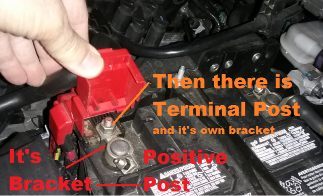
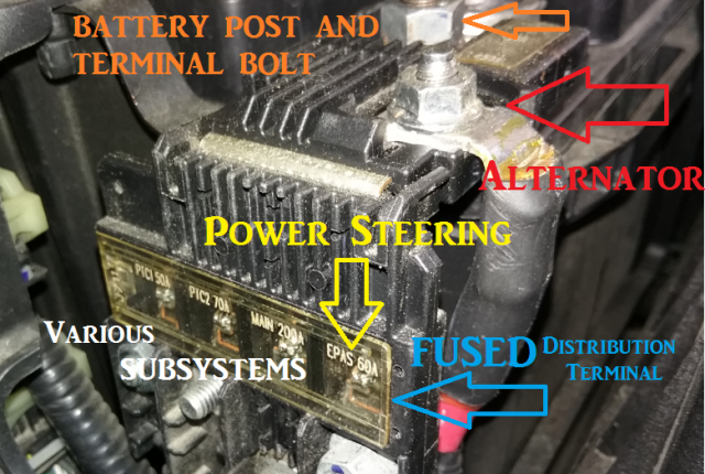
Well, were you able to keep the test light jig set up, but go to the Battery Terminal Block - that black box you have the Red cover on, and remove those wires - unbolt them, to find which SECTION of the main buss is pulling the current to make the light lite up?

The main Battery RED terminal is a 2 piece with 3 bolts - one obviously is the battery post bolt, but the second one - that one UNDER that read cap is the connection point for that main Battery bus black thingy there.

1717899381561.png

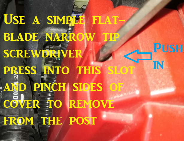
When you pull off that cap you find there are 3 posts under that cap - one closest to the battery side - if you undo it, you unbolt the main block buss from the battery. In the above it's the TERMINAL POST There are others, you will have to remove that red cap to get access to them...

1717899504337.png
That little tab when pressed outwards (away from the battery) releases the catch.
Then, to remove that cap - pull it straight up...​

It then uncovers those other bolts you need to check your TESTER to...

1717899684139.png
Look just below that plastic see-thru cover for those side mount wires.
They are bolted to the buss using fuses.​

Where I would start, is to keep the main buss bolted but disconnect the ALTERNATOR/STARTER bolt, and see if the TESTER still lights. If it does, then you leave that unbolted - but go to the EPAS - and undo that bolt - does the TESTER still Light up - then Undo the MAIN wire (unbolt it) Does the TESTER go out - then the main draw was at where the light went out - that is the system you check - so if it's Alternator and Starter wire, that system is the problem, if it went out at Main, then the system problem is further into the Fuse blocks and relays - even the SRS system - which is under MAIN on that buss block.

I see you found out about the SRS impact sensor - if that has been triggered, the SRS system is active and will need to have that sensor replaced - you can't simply remove it, it uses a loop resistor to do a self-check in the wiring as the system boots every-time you start the car, and it's why the light for it takes so long to go out - it's running that self-check loop making sure all the sensors are attached and working.

When the impact sensor goes off, several things can happen - from complete disconnect - obliterated due to impact, onto jolt and strike causing deformation - onto a bump - each type of impact gives different results from rapid deploy onto partial deploy and fuel-pump shutdown - and will prevent you from starting the car if the sensor is not replaced and allowed to be checked and re-introduced as functional - into the system - once that is done, the SRS will release control and let you operate the car normally.

Now, to me, this may be something as simple as a light from the rear trunk (luggage) not going out onto something more serious but not like SRS making you stop and prevent you from driving the car.

This is something that the wiring to the sensor may be at fault, where the insulating jacket and wire loom - but have a cut into wire(s) that makes the light stay on, the only way to know is to break down where the draw is from. So if the Alternator is bad, that light would go out the moment you pulled that wire off the battery and all you need to do is check and see if the Alternator is bad by having it tested.

The PITA is when you have MAIN is the only way the light goes out - then you'll have about 45 fuses to pull and check and at least seven relays to pull and keep out until you find the bad circuit. To help cut to the chase; review the work and work the sections that you know affect the area(s) you worked on.

As you pull, I'd look at the Owners manual, find the Fuses for Power side Mirror, Windows and the SRS system (as the example) - locate those fuses in the manual and pull them to verify - light goes out? Then that sub-system is the reason for the draw.
 
Last edited:
OP
Daveb40258

Daveb40258

New Member
Messages
46
Likes
8
City
LOUISVILLE
State
KY
Country
United States
What I Drive
2016 Fiesta Titanium Hatchback
Thread Starter #38
@Handy Andy

Hey Andy thanks for that reply. I'll get right on that.
UPDATE:
I tried to start her today because I got my new OBD2/EOBD/CAN reader. She almost started. It was hard to explain, but it sounded promising. Here is the worst part: I cleared all the codes weeks ago, and when I put the new scanner on, it said no DTCs. After trying to start it, guess which two reared their ugly heads? Yes, P0365 and P0369.


Earlier, I looked up mobile mechanics in my area on Google. I found one right up the street. There was a section on making an appointment for a crank-no-start. The request form allows you to explain what's wrong, so I spelled it all out—what was done with all the troubleshooting and diagnostics. So, the owner calls me up and says the reason he's calling is that he read my notes, and I sound knowledgeable. He was looking to hire another mechanic and thought I might be interested. I wish I were looking for a job because when you need one, they are never around. Anyway, I told him I am 65 and my patience for working on vehicles, especially today's cars just isn't there anymore.

Thanks, Andy
 

Handy Andy

Well-Liked Member
Premium Account
Messages
1,723
Likes
1,287
City
Grand Rapids
State
MI
Country
United States
What I Drive
2018 Ford Fiesta SE HB
#39
Then so you know, the Codes are telling you the reason it won't start - for when it's been down that long, the system timing is off, so it will try to boot the sub-systems while it cranks, so that means the PCM has to know where TDC is, but it can't so it doesn't let the Fuel pump or anything else start up until it knows where Cylinder number 1 is.

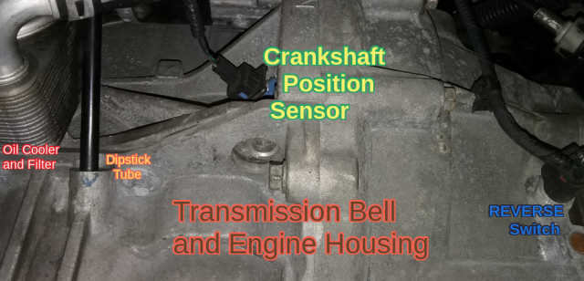
I don't know if I've asked you earlier, but does the lower bell housing - that blue connector - the one where the engine and transmission meet, make sure it's hooked up - that sensor is the CKP (Uses Flywheel) to find a zero point for cylinder 1 in relation to the crank, but the CMP which are on top, are not sending good data - so that may mean the cams are off or BENT which means damaged sensors or off-timing (jumped belt) - or the opposite, the Crank (flywheel) sensor is not sending the system good data to help it find TDC from where the magnet-to-sensor location is. That sensor is on the housing is (possibly) not sending data to help the CMP's.

To help with that CKP - review this thread - there are other links in it worth investigating too.
https://www.fordfiesta.org/threads/ford-fiesta-mk7-starting-problem-and-ckp-codes.8893/post-24203
  • Since there have been several attempts at clearing these codes does not seem to help, it may be the sensors themselves are ok, but the system has corroded wiring or bad power routing - it can't get the data from the sensors because it can't send it or retrieve it (bad power To, or poor Data or ground From)
  • Now, you said from the help of that one effort, you were able to get the system to see data - else the codes would immediately re-appear even before your started the car - there are possible options but you have to know what time these codes appear.
    • If they happen right away, then the code is caused by poor wiring (most likely-no communication to "zero out") but if it appears after you start the crank process - then the data it's getting is either bad - by poor wiring, or by actual bad data causing the code - those are due to timing which the system has found this out, not by wiring but by data it's getting back from the motor - it can only work so much from what it can get back.
So it sees errors and tries to find answers - it does that thru the CAN-Bus system. which has it's own POWER using a regulator on the BCM, Instrument Cluster, SYNC and ABS and PCM - all of these systems have a separate voltage regulation system for the CAN bus - so that light might be the reason - a tell tale the system is NOT ready to crank - something else has got to clear. The CAN bus retrieves power from the battery even when the power's off but the PCM is placed in a Wake up mode.

So what this tells me, due to the accident - the wiring or sensors have failed - so the PCM "thinks" that the timing or bad sensor - the only two issues that repeat.
 
Last edited:

Handy Andy

Well-Liked Member
Premium Account
Messages
1,723
Likes
1,287
City
Grand Rapids
State
MI
Country
United States
What I Drive
2018 Ford Fiesta SE HB
#40
Here's the Stage...

(Work in progress)

1717953901415.png
1717970474948.png
IN the above, the CKP device that looks for TDC on the Crankshaft (using the Flywheel) looks like this...

1717984716114.png
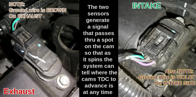
Note the color of those two wires...

Because - schematically - the two wires are a twisted pair, that is shielded back at the main Engine Block
1717977578995.png

In the above wiring diagram - the PCM accepts this device and runs it - it has a shield to protect the signal quality - it starts back at the PCM and is "open" meaning it does not terminate at both ends - one side is left open for capture of the signal at high RPM's as needed - a propagation condition can occur so they use single ended shielded wires to act like antennas to pick up this signal when RPM's are too high for "normal switch" operation - for a Hall effect device can detect the spinning magnet on the flywheel but to detect it - requires a trick used by RF engineers to help "terminate" the high-speed signal treating it like a Radio signal at higher RPM's to bring it back to the PCM for processing.
  • The device is also used as a RELUCTOR - so there is a Positive and Negative going signal result - so the signal really looks like an AC or Alternating Current signal - which it's frequency varies by the speed the Flywheel, being attached to the Crankshaft, spin rate- it can be used as a clock to tell the system to start at a known reference - from the inputs between the CMP sensors and the CKP sensor to locate and develop advance and fuel-injection timing - based upon how fast the flywheel is turning showing what the engines RPM's are

Ok, the CKP uses 2-wire with a 3rd as Shield for noise and signal pickup.

However, In the Camshaft - or CMP sensors they use three wires ... but one is used as Power Return and a type of Signal Return that helps reduce noises from Ground Loops - or better known as - they used three wires so the PCM can ground the line to itself versus having to hope the Ground at the Engine Block is quiet enough to detect the signal changes.

1717976340824.png

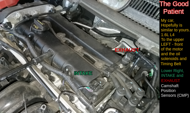
IN the Camshaft ones, due to the nature of the signal and the dynamics, uses a similar sensor but it emits a signal thru an air gap looking at where the Cam at the opposite end of the Solenoids spins. So they put a sensor in, placed in a groove, using the gap in the sensor to detect a change in the CMP - so the Solenoids when they are at rest - the CMP Speck is at TDC of the CAMSHAFT timing, when the Solenoids are active the system sees the Speck has changed so the timing is showing Advance and that then requires the CKP sensor input to be used as a second reference to TDC or when the 2nd revolution of the 4-stroke (4-cycle) motor is occuring so it knows which CMP sensor advance is at for Exhaust or Intake sides.

The process to detect is done at an end of the CAM away from the Solenoid and Advance chamber, By placing a small speck of mateiral; magnetic or other alloy metal - the sensors air-gap is placed across a flange - the cam spins a bowl-shape wheel with a tiny speck - causing just enough change in the emitted signal so it can be detected by another sensor tuned detect for that signal. The Sensor is a self-contained device that uses three wires.
  • one supplies power, and is regulated.
  • - another, the ground (return) helps provide a return to the PCM for both the signal and the power.
  • and a third is the signal result - it's what forms from the device trying to detect a spinning "dent" or dimple in the cam
  • - When the signal in the air-gap sees that speck - it changes the signal output, showing detection
    • - so it sees a distinct change when the cam spins past that dent - signaling TDC of the cam itself.

Schematically - they are like this...
1717977491503.png
IF you note the wiring color code in the photos of the Camshaft ones, they are similar and tie the main power together somewhere in the Loom - so you'll need to check those connectors for Power to the device VREF - let alone a signal ICMPS (Intake Cam Position Sensor) and ECMPS (Exhaust Cam Position Sensor) and a Signal Return (Ground - SIGRTN).​

  • Although combines, the VREF is Pin 1 on the Sensor. it is split in the loom somewhere, located at S134 where the wiring divides right under the Ignition coil box.
  • ICMPS and ECMPS are the signals themselves - output from those sensors and is present on Pin 2 (Middle)
  • SIGRTN - this is their return (Board and Sensor Ground - tied to BATTERY ground) but also provide the system with a means to trim out a noisy ground loop
    • - so the SIGRTN function serves two purposes
      • - one for return and the other is to Zero-out
      • Zero-out is the signal reference or a Null Offset.
        • It is so phase noises and other artifacts from engine noises and spikes present on the voltage lines - are taken to a known reference level - being battery ground so values it is looking for are formed are within a given range of output - and also to help the system know that the connectors are attached and that the sensor is working.
So when the CMP sensor is seeing the Advance - the Cam TDC itself is acting as an indication of Angle of ADVANCE (or retard) against the CKP sensor where the Flywheel is at one spot, but the CMP sensor for either Intake or Exhaust side - is at another - ahead (Advanced) or at the same "pulse sense" position (Retard). So the system can then determine angle of advance to fire ignition or adjust the timing of the injectors as other sensor input is used to refine the Air-fuel delivery and ignition timing advance.

So when you have those codes; the system supplies power to the sensors on top of the Motor - but only "listens" for detection on the Crank side which spins TWICE as fast as those cams do - so the speed and proximity of the signal detection is a key to making the system work as well, and as fast - as it does.
 
Last edited:


Top