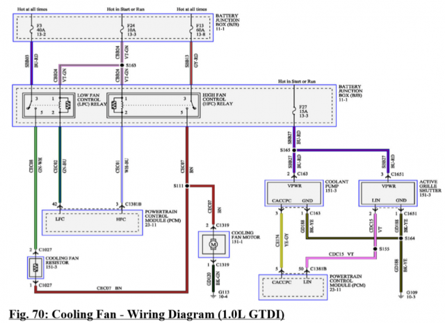
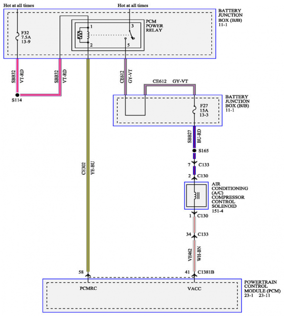
The Cooling Fan - you have one, but it uses the TWO relays. One for Cooling and One for AC they operate it, are also interconnected. One is for the Engine Temperature and then the other one is for the AC which may also contain a dropping resistor located in the housing over by the condenser core and water filter (larger long cylindrical vertical tube) used to collect the refrigerant and help precipitate out water before it gets squeezed thru a valve and orifice to generate the cooling expansion needed for the AC to work.
The Cooling Fan uses a ground lug - over by and under the Battery - it is bolted onto the frame - on the LEFT side - bolted to the engine-side (inside) of that wheel-well housing. IF the Ground wire is corroded - or the shroud is damaged - both can be keeping the fan from spinning. This jamming and poor connection can keep both the AC and Cooling (overheating) fan from even starting.
Did you check the AC pressure switch? IT won't turn on the AC FAN until the car is warned up and the ambient air temp is above 10C - but it will turn on the AC compressor below that - it will show on the AC Tell-tale light to tell you it's working.
Why the AC switch?
- - if the pressures is low the AC won't kick on because the vapor pressures are NOT high enough to operate the system without potential damage to the compressor. (A lubricant is used it can get stuck in lower sections of the system and not circulate to make it to lube those bearings and system.) The switch is like a 3-way condition switch - which is supposed to use the Tell-tale AC light on the dash to let you know :"Yes, you asked for it, so I'm operational - but with conditions".
So if the AC button pressed and the AC tell-tale is on, then the AC is ok, but colder temps - the engine needs to warm up and the outside air temp needs to be above a given temperature for the AC fan to kick on - else the system just uses the AC compressor to help warm up the motor and dry out the inside cabin side of the windows because the outside condenser side is just too cold to be effective so the fan won't kick on.
If the tell-tale is off when you try to press it on, then you have a problem.
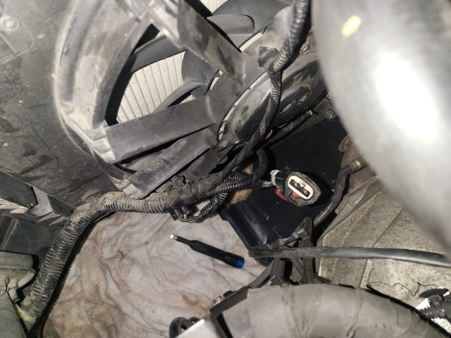
There is more to the Fan control - so if you have issues with the AC - the ENGINE Over-temperature (Cooling Fan ON Relay) condition should work independently of the AC system - but if the COMMON Ground lug used to complete the circuit to the Fan is bad, or the FAN Motor Module (Dropping Resistor) is bad, or, and worse case, the fuse to power those relays a simple 10Amp (F24) is bad - then the motor doesn't work at all - so do you have a two wire Red/Black connector? (Photo shows something else) So that means you have found the Fan connector - but you will have to dig around the shroud and make sure you have all the wires in that loom (on the shroud itself) still interconnected. That Red wire can get power from one of these relays - even both at the same time - just not all the time.
Now, that is for the 1.0L
You show a 2015 Fiesta SE - is this the 1.0L you speak of? OR do you have the 1.6L TiVCT (Naturally Aspirated) or you have the ST-line version SE? They are three different beasts.
Better check that Red Cap - the one on the battery Positive, High Current Battery connector area - it may have a blown fuse in a branch off of that.
You do know, that back at the Battery Junction Box (The High current side of the main Engine Bay Fusebox) , you have several fuses F3 - 40A (Low-Speed Hi-Amp), F13 - 60A (Hi-Speed Hi-Amp), F24 - 10A (Relay power) which Powers Relay R5 and R7 (Emissions branch to PCM) and F27 - 10A (Active Shutter - Coolant Pump)
But you will have a separate harness to the fan shroud to handle the dropping resistor which routes (loops) back as the (READ: Your) RED wire to the Fan connector, and from that loom, even have a branch off of that to go to the Active grille shutters. Remember I mentioned that the Dropping Resistor that gives the Fan Low-speed - speed, is also mounted in the shroud.
Ok...there are some questions...
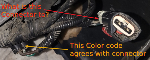
Just not sure which one of these connectors are the ones that are OEM. One on the bottom agrees with the schematic. But the other one left open in the photo - where did that go?
You may have struck something under the vehicle or rolled over some debris that can affect the integrity of the wiring.

